Turn off the monitor and remove the SD card
Start the StarliteHD and hold the switch down until full reset appears on the sreen

We also recommend to format the SD card after resetting the StarliteHD

StartileHD records by default in H264.
Post conversion to mp4 or mkv is possible. In the video gallery, press the Convert icon and select a video file to convert

  • Activate the VirtualHorizon in the Tools menu
  • Double tap on the CAL text, on the right hand side of the yellow bubble
  • Check that the monitor is connected to the EXT connector on the camera
  • In the camera menu, go to MONITORING >> SDI and check that SDI 1 image and/or SDI 2 image are set on Processed
    • This will enable the dialog protocol between the camera and the monitor
    • Note: the Starlite’s dedicated ARRI menu will only be present on the SDI output that has been set to Processed

Step 1

Plug the SD card into your computer.

Please read the latest realease requirements before updating.

Uncompress the latest software release (downloaded file is in zip format) using your archive utility application.

Open the uncompressed folder then copy the file ending with .tar.gz and paste it at the root of the SD card.

Do not rename the file on the SD card.

Step 2

Plug the SD card into the monitor.

Turn ON the monitor then push down the menu button.

Select the Settings icon     then choose Update.

Validate your choice and wait...

Step 3

During the update operation, you can read the following information

At the end of the update, the monitor displays the report below
Troubleshooting
In case of faulty update, your monitor will show one of the following messages.
If you still have an issue after several attempts, contact us.
Download user quick start guide :
StarliteHD5 standard version
StarliteHD5-ARRI
At startup, the StarliteHD software version (build) is displayed on the bottom right corner of the screen
For version prior to 3.08
Start the Stargate and press Adjust + Technical keys until "Full Reset" appears on the sreen

For version 3.08 and up
Start the Stargate and press Adjust key until "Full Reset" appears on the sreen

The VirtualHorizon displays in the Body-Rig View.

  • Press the joystick once to launch the 0CAL
Stargate records by default in H264.
Post conversion to mp4 is possible. In the video gallery, select record you wish to convert then push MP4 icon on the top right corner
  • When reading SD card on computer, converted files are under export folder.

  • Check that the Transvideo logo displays at startup – front LED should also turn green for about 3 seconds
  • Push the Inputs button and check that the correct video input is selected
  • Check the BNC cable
  • Check that the output format of the camera is supported by the monitor


Step 1
Plug the SD card into your computer.
Please read the latest realease requirements before updating.
Uncompress the latest software release (downloaded file is in zip format) using your archive utility application.

Step 2
Open the uncompressed folder then copy the file majStargateNew.vxxx.tar.gz (majStargate.vxxx.tar.gz for 2.14 and erliear version, xxx stands for the version) and paste it at the root of the SD card.
Notes : Two files are needed for the update V2.01
Do not rename the file on the SD card.

Step 3
Plug the SD card into the monitor.
Go to Technical menu then choose Update (Inputs button).
Validate your choice and wait.

Step 4
Do not remove the SD card during update process.
The monitor displays "Please wait, upgrade in progress" during the update process.

Step 5
The monitor may not restart automatically after update.
You can restart it manually 5 minutes after all LEDs stop blinking.
At the end of the update, you can check the loaded firmware version check in Technical / Infos.

Troubleshooting
If the update message is displayed for more than 5 minutes.
Turn off then restart the monitor. At startup it runs a "Force update". Then go to step 5
In case of faulty update, contact us.
Start the monitor and press Technical + Return keys until "Force Update" message displays
Reset of every radio links can be obtained by pressing the “RESET” button for a few seconds on the Titan HD2 Rx side.
It can be useful to do when pairing issues are encountered (when a Rx unit has been paired with too many Tx units).

Guide 1 : Pair 1  StarliteRF with 2 or more TitanHD2 Tx
Up to 2 Tx can be paired (or registered) with a StarliteRF, in order to be swapped by use of smart corner A/B (smart corners menu) or tool A/B (tools menu).
Nevertheless, if you use only 1 Tx at a time, you just have to pair it and it will be automatically displayed.
Procedure to set up properly Tx in order to use swap Tx function (if you use a single Tx, just pair it regardless if Tx A or Tx B is selected) in "Menu parameters / TX pair":

  • Switch on your 2 Tx, we recommend a distance of 10 ft (3m) between StarliteRF and Tx. Press icon “Reset Tx”
  • Press icon “Tx A”, press “REG” button on Tx unit A until blue led blinks fast (2s).
    Wait until the message “Press OK” appears on the monitor, and then press icon “OK”
    The first Tx has been registered. Icon “Tx A” is now marked “Tx B”
  • Press icon “Tx B”, press “REG” button on Tx unit B until blue led blinks fast (2s)
    Wait until the message “Press OK” appears on the monitor, and then press icon “OK”
    The secondth Tx has been registered, and you can swap them with A/B icons.


Guide 2: Pair 1 TitanHD2 Tx with 1 or more StarliteRF
Up to 4 Starlite RF can be paired (or registered) with a Titan HD2 Tx:

  • Switch on your Tx, we recommend a distance of 10 ft (3m) between StarliteRF and Tx.
  • Switch on StarliteRF 1
  • In "Menu parameters / TX pair", press icon “Tx A”, press “REG” button on Tx unit A until blue led blinks fast (2s)
    Wait until the message “Press OK” appears on the monitor, and then press icon “OK”
  • Repeat the same procedure for the other StarliteRF.


Guide 3 : Pair 1 TitanHD2 Tx with 1 or more TitanHD2 Rx

  • Switch on your Tx, we recommend a distance of 10 ft (3m) between Tx and Rx.
  • Switch on TitanRX and connect a monitor to the output.
  • Press “REG” button on TitanHD2 Rx unit until blue led blinks fast (2s) 
  • Press “REG” button on TitanHD2 Tx unit until blue led blinks fast (2s) 
  • When message “Press OK” appears on the monitor,then press “REG” button again on TitanHD2 Rx
  • Repeat this procedure for the other TitanHD2 Rx.

Full Reset

  • Connect the monitor to a power source (monitor off).
    Press the adjust (ADJ) key
    Switch on the monitor while keeping pressed the “adjust” key until the display shows “FULL
    RESET”
    The monitor is back to its factory default settings. This procedure totally erases all user setup in the
    memories.

Preset
  • Go to menu MEMORY >> PRESET
  • Select PRESET ALL INPUTS if you want to reset the settings you made on all the video inputs (SDI, CVBS, ACC …)
  • Select PRESET SELECTED INPUTS if you want to preset only the current video input settings. 
  • You will be asked to validate your choice: select YES and press the rotary knob

    Note
    : the settings saved in memories MEM1, MEM2 and MEM3 will not be affected

1st method
Go to menu TOOLS >> HORIZON and select 0 CAL

2nd method:
Go to menu TOOLS >> HORIZON and select 0 CAL ON TAP: ON
Adjust the sensitivity of the TAP with the 0 CAL ON TAP THRESHOLD menu (1: weak, 4:strong)
Exit the menu and tap on the screen, above the Transvideo logo

3rd method:
Long push on the User push button
Navigate with the F4 button and select HRZ:0CAL by pressing F2
Exit the menu by pushing the rotary knob
Press User button to launch the 0CAL of the VirtualHorizon

Step 1

• Uncompress the content of the 0CAL-client.zip file (download) at the root of a clean USB stick and connect it to the monitor

Step 2
• Go to menu HELP -> ADVANCED UPDATE ->FORCE UPDATE and follow the instructions on screen

Step 3
• Switch the monitor off/on, wait for the Production menu

Step 4
• Select F5 ADVANCED CONFIGURATIONS

Step 5
• Select F1 to start a 0CAL
You can use a mechanical bubble or a smartphone with any application giving a true horizon level.

!!Wait at least 30 seconds before starting the calibration. "Angle real" must be very stable and "Sensor init" information gone.!!

Step 6
• Select F2 to start a 0CAL in reverse mode.

Step 7
• Select F4 to quit menu


Step 8
• Uncompress and copy the content of the CineHD latest release at the root of a clean USB stick and connect it to the monitor

Step 9
• USelect F7 FORCE UPDATE and wait for 2 green leds.

Step 10
• Switch the monitor off/on, go to menu HELP -> UPDATE and follow the instructions.

Step 11
• Switch the monitor off/on, the update is done

Notes

  • In the menu HELP -> MONITOR INFO, check that you have the following versions :
    • Mainboard soft micro1 : 7.26 and up
    • Mainboard soft micro2 : 2.21 and up
    • Mainboard firm : 10.11 and up

Step 1
• Turn the VH3 On: switch must be orange.

Step 2
• Turn the monitor On.

Step 3
• Go to menu TOOLS -> BLUETOOTH. If the device is not auto-connected, select UPDATE DEVICE; the monitor is searching for available Bluetooth devices.

Step 4
• You should see a device called "VH3".

Step 5
• Look at the number in front of the device name, then select this number in menu SELECT DEVICE NO: the monitor should show "VH3 connected".

Step 6
• The switch of the VH3 should be green when connected.

Step 7
• Go to menu TOOLS -> HORIZON -> SENSOR : WIRELESS HORIZON Xaxis or Yaxis.

Step 8
• Select your preferred STYLE and enjoy!

Notes

  • When you connect the module with a USB cable and then turn the module ON: the switch is blinking green and the VH3 module is in the update Mode. 

Refer to the App note for VH3 Update (work in progress). 


  • When powered by USB or mini Lemo2, the module charges its battery:
    • Red Led: still charging
    • No Led: charged


  • Once powered and turned ON, if you switch the VH3 Off, it takes a little while before the BLUETOOTH menu indicates "No Device Connected".


  • Once the monitor and the VH3 have been connected, both devices will auto-connect when switched ON.


  • When mounted on a steadicam and powered by mini lemo2, both monitor and VH3 can be powered simultaneously. Detection is almost immediate.


The VH3 is not compatible with the StarliteHD.

There are several possible sources for the Tally information : REC Flag on SDI, voltage level on the ACCessory Run pin, Voltage level on a GPI pin.

Configuring the SDI Tally display:

  • Go to menu TOOLS >> TALLY >> SDI and select between REC MODE /CUSTOM MODE / ON AIR MODE / OFF
    • Note: you can adjust the REC MODE graticule position
    • Note: CUSTOM MODE display is configurable: choose between FRAME 3 / SQUARE / DUAL SQUARE / RED DOT


Configuring the ACC Tally:

  • Go to menu TOOLS >> TALLY >> ACC and select between CUSTOM MODE / ON AIR MODE / OFF
    • Note: CUSTOM MODE display is configurable: choose between FRAME 3 / SQUARE / DUAL SQUARE / RED DOT
    • Go to menu TECHNICAL >> GPI >> ACC and select the trigger condition: LOW / HIGH / LIGHT SENSOR


Configuring the GPI Tally:

  • Go to menu TOOLS >> TALLY >> GPI and select between CUSTOM MODE / OFF
    • Note: CUSTOM MODE display is configurable: choose between FRAME 3 / SQUARE / DUAL SQUARE / RED DOT
    • Go to menu TECHNICAL >> GPI:
    • select the GPI function: FUNCTIONx : TALLY RED (pin x on the GPI connector J002)
      • Note: each GPI pin (1 to 4) can be assigned different functions. Make sure to have the TALLY function affected to only ONE GPI.
      • Note: TALLY RED is a different FUNCTION than TALLY GREEN; therefore they can be affected to different pins.
      • Select the trigger CONDITIONx: LOW STATE / HIGH STATE / RISING EDGE / FALLING EDGE / LIGHT SENSOR / NOT ACTIVE


Example:

The TALLY signal is connected to pin 2 of the J002 connector, and the information will be a positive voltage level on the pin (12V max.).

  • In menu TOOLS >> TALLY >> GPI,
    • FUNCTION2 : TALLY RED
    • CONDITION2: HIGH STATE

If you wish to have a second TALLY information, say on pin 4 of the J002 connector:

  • In menu TOOLS >> TALLY >> GPI,
    • FUNCTION4 : TALLY GREEN
    • CONDITION4: HIGH STATE
  • Check that the Power led is green at startup
  • Check that the Transvideo logo displays at startup
  • Push the Input Sel button and check that the correct video input is selected
  • Check the BNC cable
  • Check that the output format of the camera is supported by the monitor


See below steps fo CineMonitorHD / CinemonitorUHD and CineMonitorHD 3DView with software 6.xx / 7.xx / 10.xx / 12.xx

For earlier versions, please contact us

Before updating, please ensure that you have a FAT32 formatted USB drive.
All dowloaded and extracted files must be located at the root of the USB drive (not in a folder).
It is mandatory to read requirements
for each software release and ensure to download the appropriate package.

Upgrade from a major version to another one (eg. SW 6.xx to SW 7.xx) is not free of charge and depends on the monitor model and isntalled hardware.
Please contact us for more information

Update procedure for CineMonitorHD and CineMonitorUHD 7.xx

Also valid for 6.xx / 10.xx / 12.xx

All software and firmware as well as input board updates are possible by the use of a formatted FAT32 USB drive.
A USB adapter is delivered with your product. If you have lost yours, you may order a new one (ordering code 571TS0015).

Read below the steps to reproduce in order to update all software and firmware on your monitor.

Step 1
Get the latest compatible software package with your monitor.
An update package is a .zip file that contains softwares and firmwares that are compatible each other. It can be downloaded on this page. You can also ask it directly to your local Transvideo representative.
Uncompress the .zip using your archive utility application. Then paste all the files at the root of a USB key.

Step 2
Plug in the USB key on the left SIDE of the monitor by using the mini USB adaptor (included with your product) and start the monitor.

CinemonitorHD, CinemonitorUHD side USB port

Step 3
Go to MENU / HELP and select UPDATE
The update starts. Do not turn off the monitor neither remove the USB key until the update ends. Follow the instructions on the screen.
Wait for 2 green leds (Power & Tally leds next to the knob) and restart the monitor.

CinemonitorHD - CinemonitorUHD Tally and Power lights

Step 4
Go to MENU / HELP / MONITOR INFO and verify that the software and firmware versions match with the update package.

Notes:
The update duration may vary between 3 minutes and 6 minutes depending of your hardware and files present on the USB key.
During the first startup following an update, the monitor automatically performs a backup of all firmwares and a full reset. It can take several seconds before your monitor reach its normal operation.

Precaution:
We advise you to format your USB key before an update to avoid hidden files problems.
Do not rename files on the USB key.

If you have CinemonitorUHD, check the input board Software and Firmware version
Menu Help >> Monitor Info

Update the UHD input board if the version is prior to the latest available downloads

How to update CinemonitorUHD input board

Before updating your UHD input board, go to HELP >> MONITOR INFO menu and check version and compatibility according to the technical requirements.

Step 1 
Download the latest update zip file
Uncompress .zip file using your archive utility application.
Copy/Paste files at the root of a USB key. Make sure the files SUHD_update.bin and FUHD_update.bin files are present
Do not rename the file on the USB key.

Step 2
Start the monitor and if possible, connect it to a video signal
Go to menu HELP and select UPDATE

Step 3
Plug the USB key in the back of the monitor, in the USB connector of the input board, using a mini USB adaptor.

CinemonitorUHD input board USB port

Step 4
Restart the monitor.
The update starts.
Green LED should light up on the USB input board during the update process, considering a newer software / firmware has been detected on the USB key.
Update is finished when the screen displays pictures and the USB LED is OFF.

Step 5
Go to HELP >> MONITOR INFO menu and check version.

Troubleshooting / Force update

Force update may be useful in case of update failure
Follow above step 1 to step 3

Step 4
Go to menu HELP >> ADVANCED >> FORCE UPDATE

Step 5
Plug the USB key in the back of the monitor, in the USB connector of the input board, using a mini USB adaptor.

Step 6
Restart the monitor.
The update starts.
Green LED should light up on the USB input board during the update process. The software and firmware found on the USB key will be uploaded.Update is finished when the screen displays pictures and the USB LED is OFF.

For CineMonitorHD Evolution with SW 6, upgrade are available to enjoy the benefits of SW 7

  • Upgrade CineMonitorHD Evolution SW 6.xx to SW 7.xx
    P/N 914TS0026 - 600€
  • Upgrade CineMonitorHD Evolution SW 6.xx to SW 7.xx including VirtualHorizon2
    P/N 914TS0025 - 900€

Update procedure for CineMonitorHD with software 5.xx

Firmware and software updates are possible by the user with a USB key and a USB cable.
A USB adapter is delivered with your product. If you have lost yours, you may order a new one (ordering code 571TS0015).
The cable used for the update is a standard USB to mini USB cable. We can supply this cable (ordering code 906TS0080).
Read below the steps to reproduce in order to update software and firmware on your monitor.

Preliminary steps
› Download the latest software update package 5.xx
Uncompress the .zip file using your archive utility application
To perform the software update, the Atmel Flip environment is necessary.
Atmel Flip will be installed in the directory \Program Files\Atmel.

Update package content

SCHD5xx-MB2-1.hex
SCHD5xx-MB2-1.bat
FCHD5xx.rpd

Software update

Step 1
Switch on the monitor while keeping pressed the rotating key. The screen remains black and the monitor is ready for the update.
Then connect the monitor to the PC with a USB cable.

If the driver Atmel DFU is not installed, you will be asked to install it.

On the "Found New Hardware Wizard" Windows application, choose to "Install from a list or specific location".

Then select "Search for the best driver in these locations" and "Include this location in the search". Select the directory \driver-atmel-DFU that is attached to the Atmel Flip ZIP archive you have downloaded. Then click on "Next"

The driver installs itself.

Step 2
Double clic on the appopriated .bat file:

SCHD5xx-MB2-1.bat

If you receive the files by email, the .bat files have a .trsv extension for security reasons: please change their extension to .bat
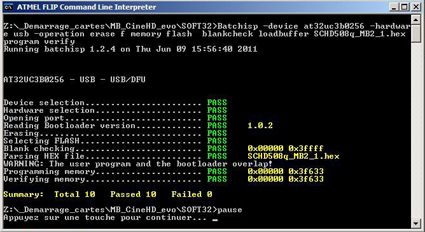
Step 3
The following window appears and the software update starts. When you are prompted to "press a key to continue", check that all action has the "PASS" mention.

Step 4

Unplug the USB cable an restart the monitor. The monitor performs a full reset before reaching its normal operation.

Firmware update

Step 1
Copy the appropriated firmware file on a USB key: FCHD5xx.rpd
The file must be renamed on the key: FCHD.rpd

Step 2
Connect the USB key on the monitor with a USB adapter (included with your product).

Step 3
Switch on the monitor while keeping pressed the F1 key.

Step 4
When a red led switches on, release the F1 key and wait for two green leds. The update starts and ends automatically.

Step 5
Unplug the USB key and restart the monitor. The monitor performs a full reset before reaching its normal operation.